|
[an error occurred while processing this directive]
[an error occurred while processing this directive]
|
|
Contents below
on this page:
1. Some Thoughts On Display Layout Track Plans [below]
2. Samples From Discontinued 'T1' Track Plan Set [below]
3. Approximate Track Requirements For Plans In T1 Track Plan Set [below]
4. Two Additional Track Plans [below]
|
Discontinued 'T1' Track Plan
Set
1. Some
Thoughts On Display Layout Track Plans
Introduction
Introduction
Putting this set of
drawings together into a formal set of track plans was the idea of Ed
Zellner, so he gets part of the credit (or discredit) depending on
whether you find any value in this collection of ideas.
We try to "tangle" the
tracks loops up as much as possible, as opposed to just running trains
in concentric circles. Using trestles to operate on different levels,
plus automatic block controls to operate multiple trains on the same
track, we can get some interesting visual effects, in spite of the
constraint of being required to set up and tear down the layouts within
a few hours.
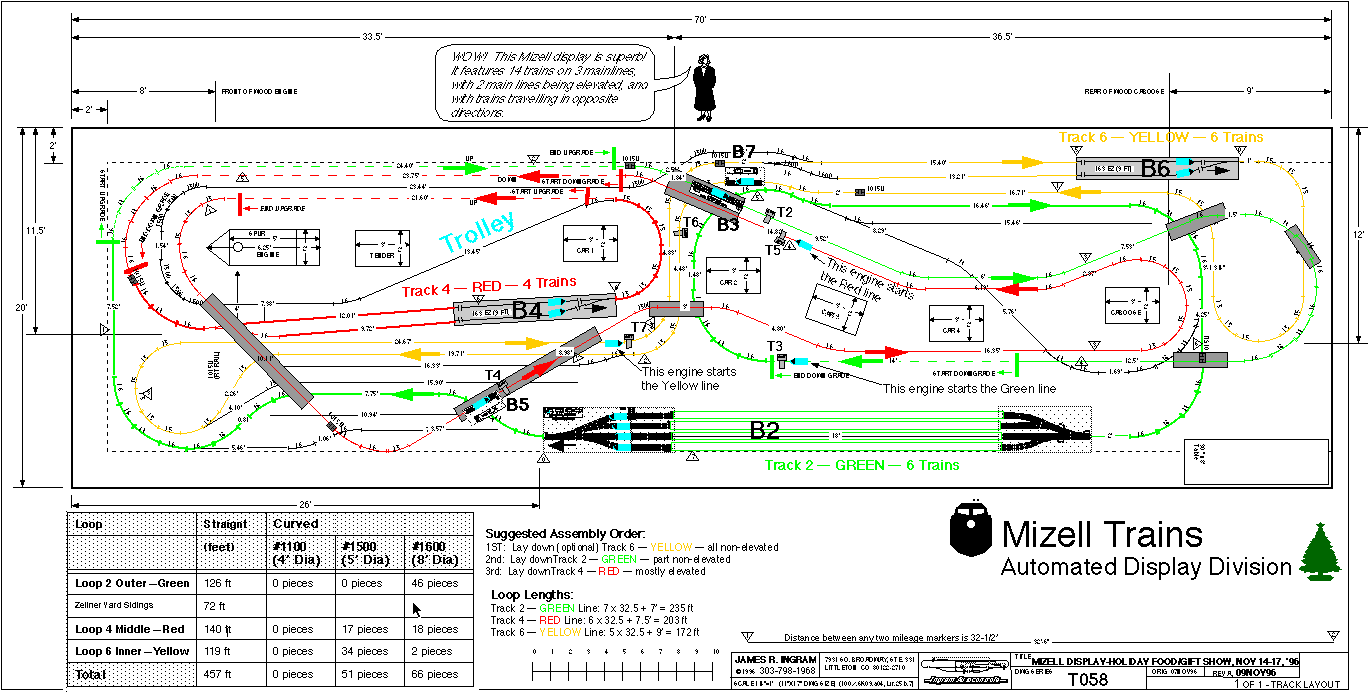
For reference, the 3
standard G scale track circle radii' are shown in the following figure.
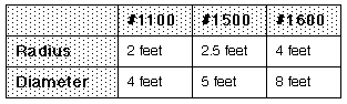
Fig 22b -- Common Track Radii
The General Theme
Some of these
layouts have a general "theme" to the track plan, which I will now try
to point out.
These layouts with "the
theme" have have typically 3 loops.
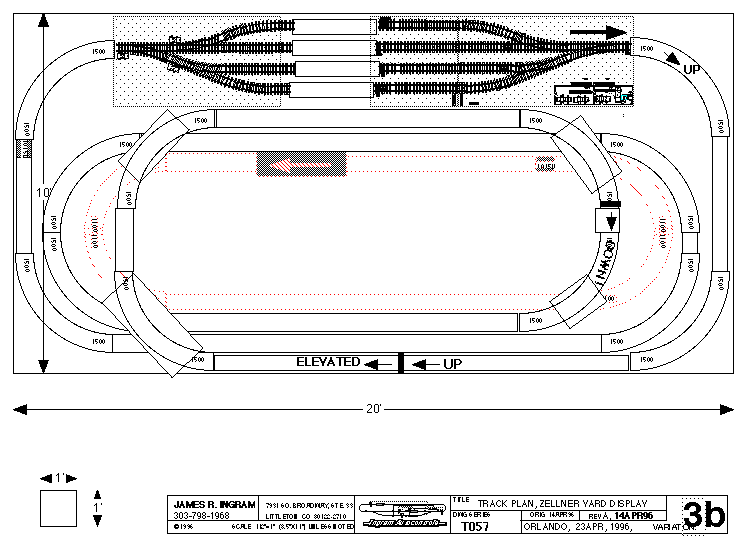
LOOP 1: "Loop 1" on the
outside, generally goes around the outside perimeter, except that it
the rear it comes into the inside, as shown in the following figure.
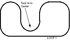
Figure 22c -- Outside "Loop 1"
This "tuck in" in the
rear allows us to visually "tangle" this loop with the rest of the
layout, instead of looking like a separate isolated loop just running
around the outside.
LOOP 2: The 2nd
component is a "Loop 2" that runs inside of Loop 1 and must be elevated
so that it can climb over top of Loop 1.
The following figure
shows the elevated Loop 2 added. Loop 2 typically starts climbing
around point "2A", and comes back down to ground level around point
"2D". In addition, you can elevate the outside "Loop 1" between points
"1A" and "1D".
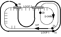
Figure 22d -- Adding The Elevated "Loop 2"
Squeezing In Loop 3
If you have a
larger space, you can often squeeze in a "Loop 3" that uses the space
left over on the inside, as shown in the following figure.
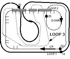
Figure 22e -- Adding "Loop 3" On The Inside
Examples Of This Theme
Comments About Notation
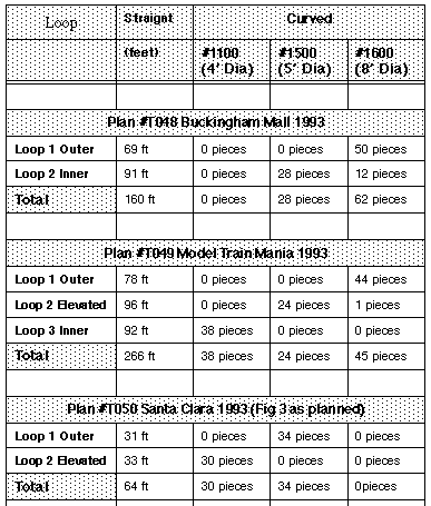
Some of the
drawings use a notation such as, for example, "T050". This is short for Track Plan # 50.
Examples
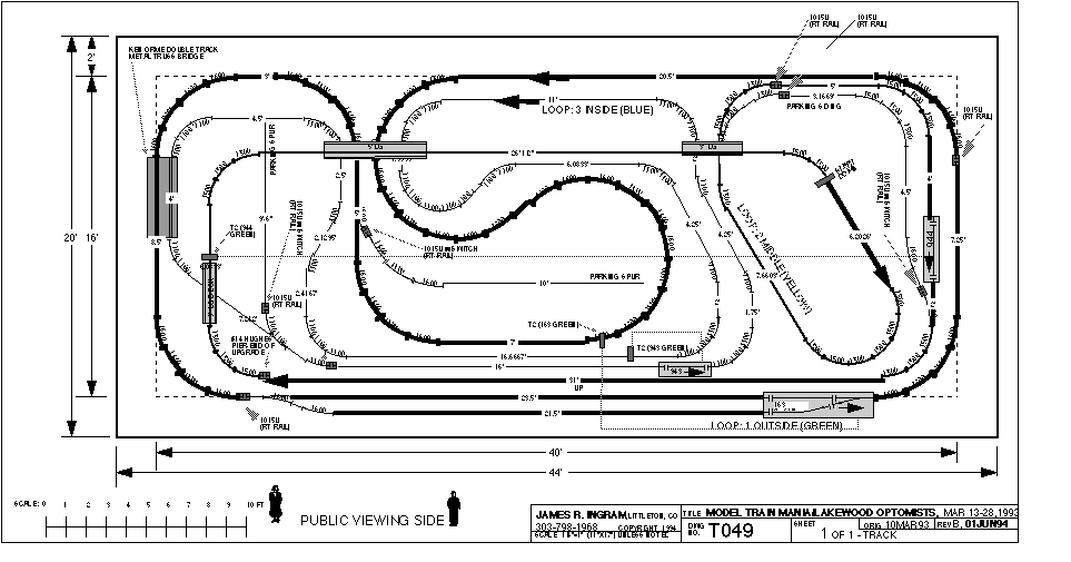
Plan T049 titled
"Model Train Mania/Lakewood Optomists" in this booklet shows a plan
that has all 3 loops, in about the minimum space this can be done with
the outide loop being 1600 radius.
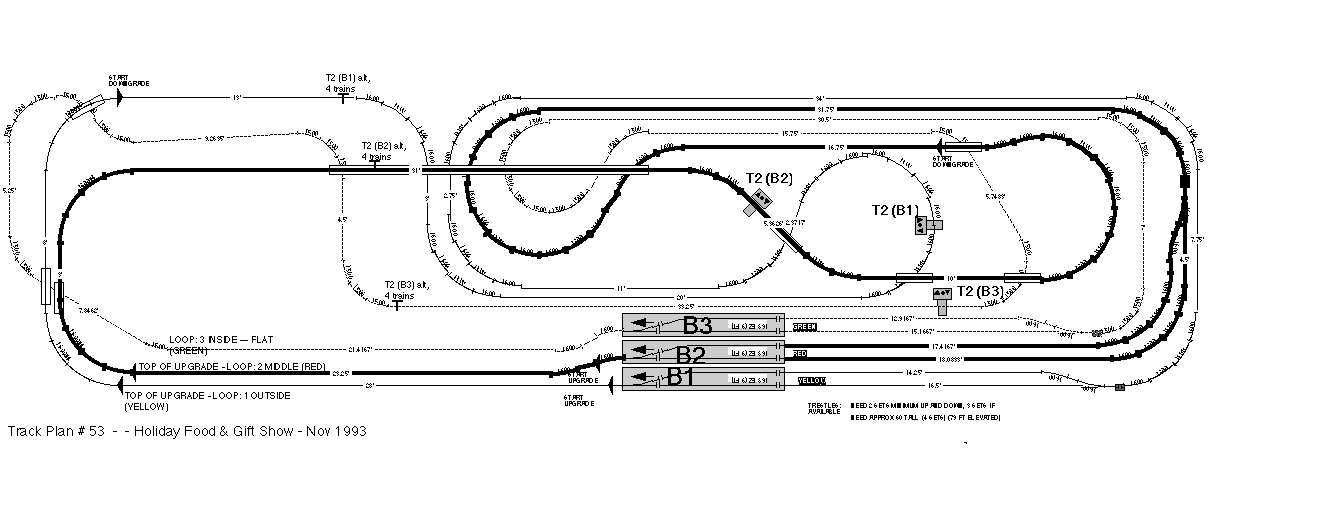
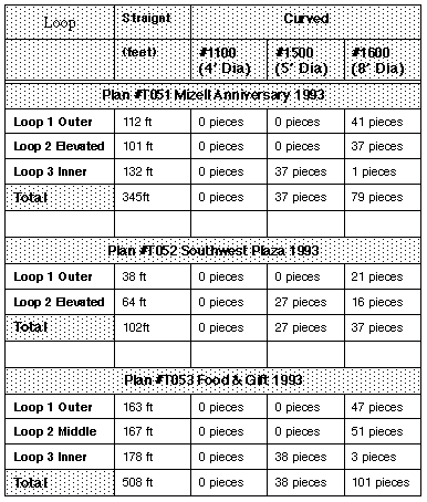
Layouts T051 and T053
also use this 3 track theme, and these two layouts also have the outer
Loop 1 elevated in addition to the always-elevated Loop 2 as described
above.
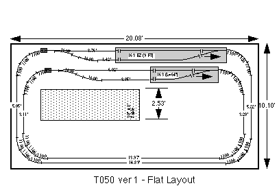
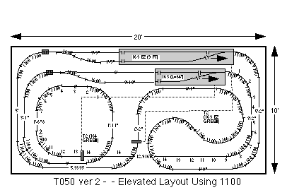
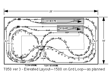
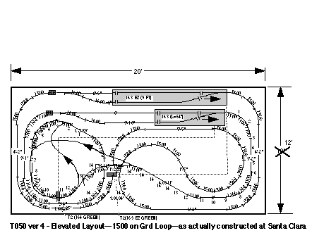
Track Plan T050 "Ninth
National Garden Railway Convention" uses this theme, but omits the
inside Loop 3 due to its small size.
Uphill Rights Better
than Uphill Lefts ?
Whenever the
track plan has an incline, I try to do the "climbing" on straight
track, as the engines can pull significantly more cars if they do not
have to pull the train through an uphill curve. If an uphill curve is
unavoidable, I try to use an "uphill right" in preference to an "uphill
left". This is because the LGB engines have the traction tire on the
left side, which causes the engines to have somewhat of a built-in
tendency to "torque" to the right. So by curving the track to the
right, you are guiding the engine in the way the traction tire is
already trying to make it turn.
Master Loops and Slave
Loops
On some of these
layouts, where both outside Loop 1 and middle Loop 2 climb a grade side
by side, we have modified the controls slightly so that one loop is a
"slave" of the other loop.
Plan T045 shows outside
Loop 1 slaved to middle Loop 2 by moving the T1 and T2 track contacts
of the Model 944 automatic block on the outer loop, and relocating them
to the middle loop. This arrangement prevents a train from exiting the
944 block on the outer loop until a train exits the 163 switching block
on the middle loop. The net result is that the middle Loop 2 "cues" the
outer Loop 1, so that two trains climb the upgrade more or less side by
side.
Plan T051 shows the
middle Loop 2 slaved to the outside Loop 1, by moving the T1 and T2
track contacts of switching block B2 to the outside loop. In this case,
outer Loop 1 cues middle Loop 2, with the same objective of having two
trains climb the upgrades simultaneously.
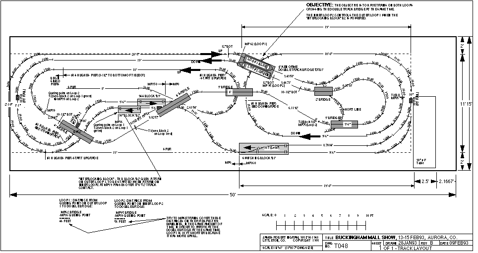
Plan T048 shows an
arrangement where the middle Loop 2 cues the outer Loop 1, where the
two loops are running in opposite directions.
The objective is to
have the trains travelling in opposite directions meet at the same time
at the "high bridge". This idea works, but I question whether the
visual results justify the additional complication to achieve it.
In general, this
"cueing" seems to produce a more impressive visual result when the two
connected loops are going the same direction on side-by-side upgrades.
|
2.
Sample Track Plans
What's
Included In This
Section
I have included
samples of some the the 14 plans in the Track Plan Set, as I have most
of the drawings on the computer. Most of the photos, however, are not
included, as I do not have them scanned.
%11
|
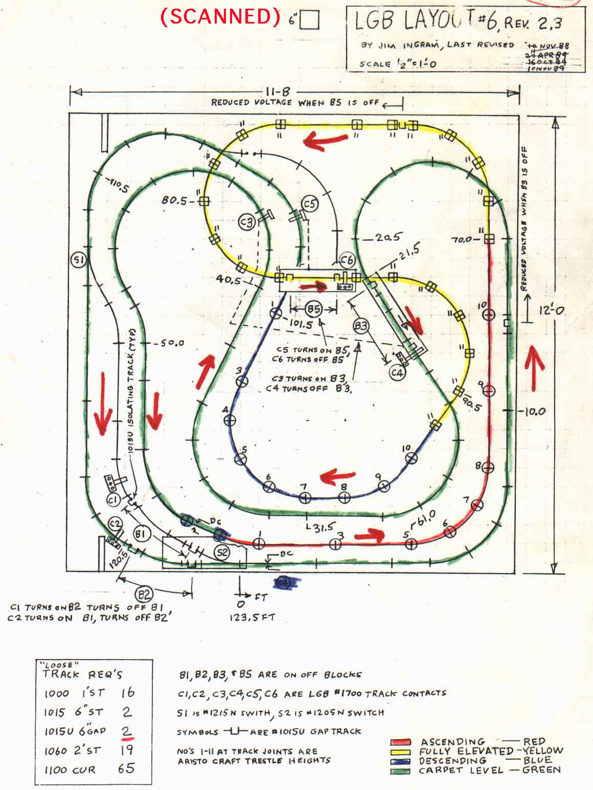
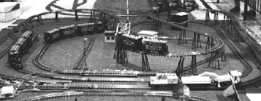
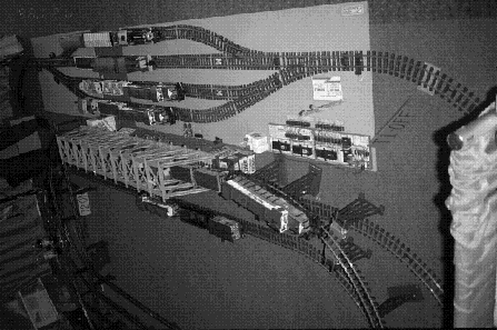
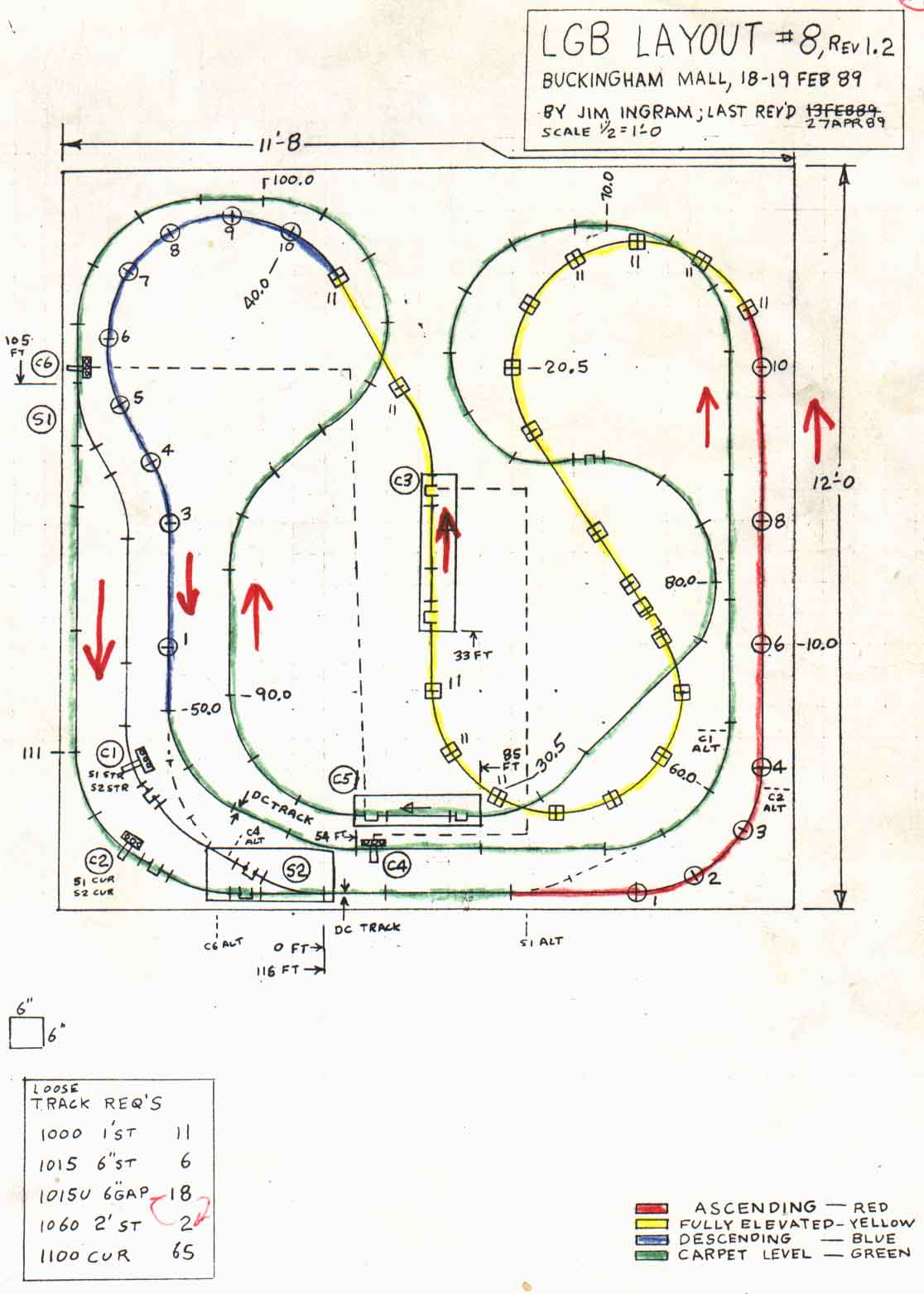 Figure 8A
- The hand-drawn Plan #8
Figure 8A
- The hand-drawn Plan #8